 1
1
 2
2
 3
3
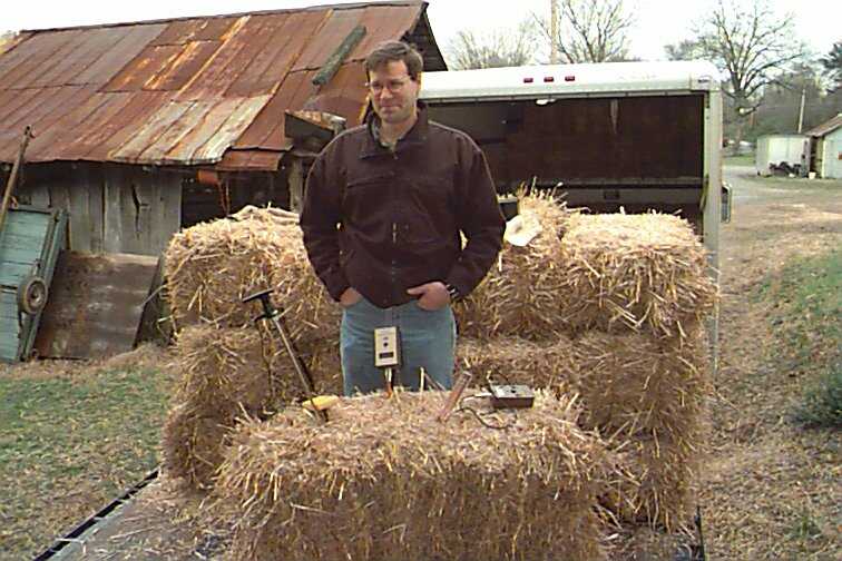
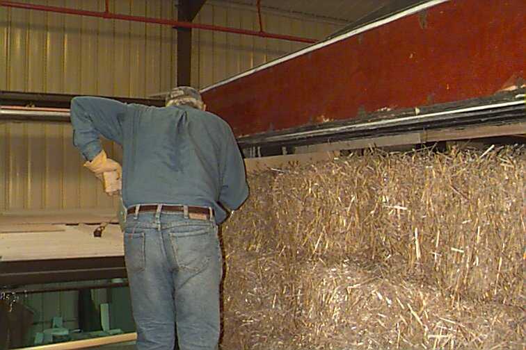
1. Getting straw bales from a local (East Tennessee) farm barn.
2. Testing straw bales for moisture content.
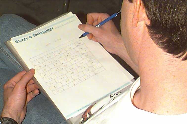
3. Bales were numbered and labeled by moisture content.
 4
4
 5
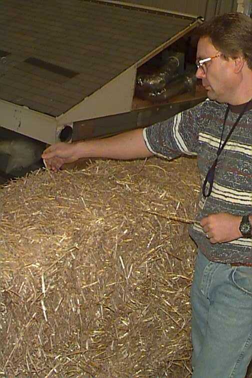
5
 6
6
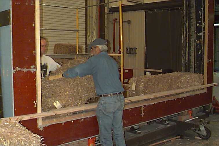
4. Bales were organized and placed in the frame by moisture content.
5. Bales were stacked inside the wall test frame.
6. Wall test frame inside the Building Technologies Center test facility.
 7
7
 8
8
 9
9
7. Bales were aligned to make a flat wall surface.
8. Bales were measured for uniform width.
9. Cracks between bales were stuffed with loose straw.
 10
10
 11
11
 12
12
10. Bales were vertically compressed by tamping or pushing down.
11. Bales were held together with steel rods called reenforcing bar (rebar).
12. Sensors with long wires were stretched to reach outside the frame.
 13
13
 14
14
 15
15
13. Sensors were inserted into bales at pre-specified locations.
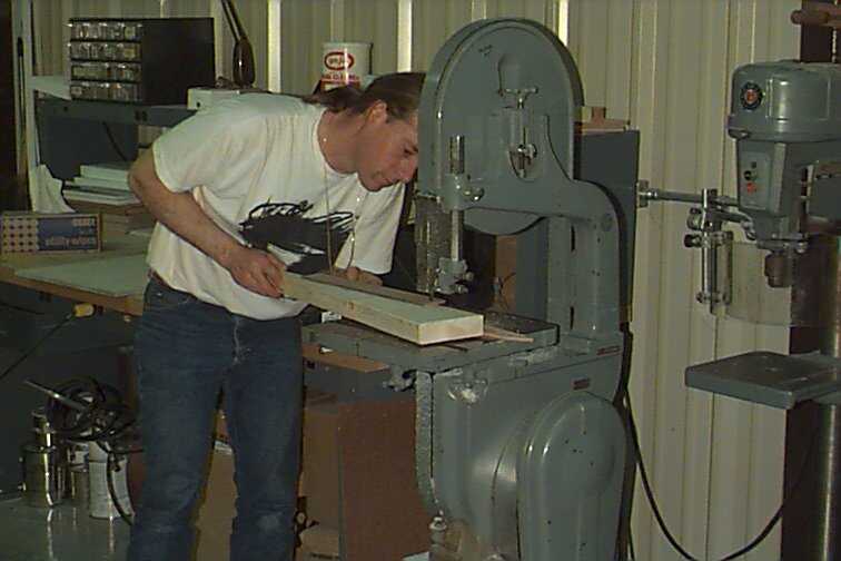
14. Cutting a straw bale in half.
15. Tamping or manually compressing the top row with a board.
 16
16
 17
17
 18
18
16. Seven of the eight rows of bales in place.
17. All eight rows of bales in place.
18. Cutting wedges which will keep the top row in place.
 19
19
 20
20
 21
21
19. Inserting the wedges above the top row.
20. Wall with top wedges in place.
21. Securing the sensor cables to the side of the wall.
 22
22
 23
23
 24
24
22. Marking the location of the sensors to ensure proper placement.
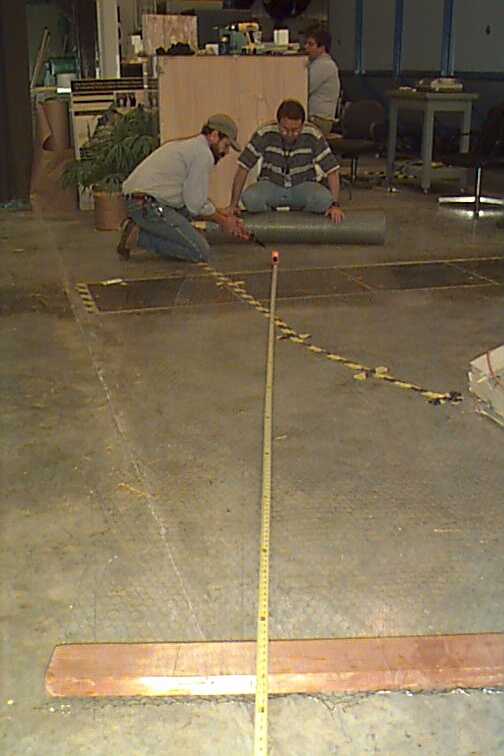
23. Cutting a width of wire mesh to attach to the face of the wall.
24. Attaching the wire mesh to the wall surface.
 25
25
 26
26
 27
27
25. Wire mesh in place on wall face to help stucco adhere.
26. Insulating the spaces between the top wedges.
27. Compressor truck ready to receive concrete and spray concrete.
 28
28
 29
29
 30
30
28. Cement was transferred to the compressor truck.
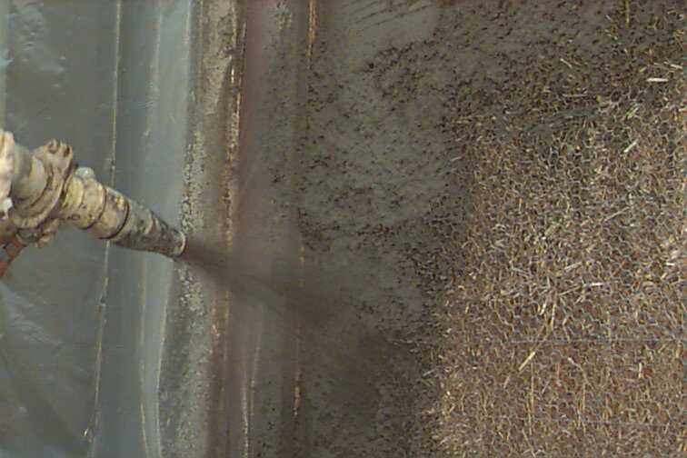
29. Nozzle used to spray the cement as stucco.
30. Plastic protected the frame from cement spray.
 31
31
 32
32
 33
33
31. Plastic protected the building from cement spray.
32. Pressurized cement is applied to the wall as stucco.
33. The stucco adheres to the wiremesh and straw.
 34
34
 35
35
 36
36
34. Stucco has a rough surface before smoothing.
35. Stucco being smoothed with a long board or screed.
36. Stucco being smoothed with a hand trowel.
 37
37
 38
38
37. Stucco surface after smoothing.
38. The wall gets turned to stucco the other side.