
- Number 313 |
- June 7, 2010
Precision Models Aid Cleanup
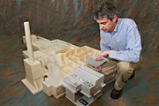
8-foot long, 4-foot wide model
of the entire underground
portion of the R Reactor
complex.
In a project that’s part engineering, part history detective, and part high-tech craft project, the U.S. Department of Energy’s (DOE) Savannah River National Laboratory (SRNL) is creating computer-produced scale replicas of the Savannah River Site’s reactor buildings to support the American Recovery and Reinvestment Act project here. Use of these models as SRS plans final disposition of the reactor facilities is saving time and money.
The SRS R and P Reactors were built in the early 1950s and shut down in 1964 and 1988 respectively. Using stimulus funding for cleanup of SRS, the reactors are scheduled for in-situ decommissioning. Below-grade areas will be stabilized by filling them with specially designed grout. Portions of the above-ground facility will be demolished, while other portions will remain standing, sealed against access by humans or animals, to serve as a protective cover for grout-stabilized below-grade areas. Grouting of the belowground areas calls for a precise understanding of their rooms, walls and other structural elements.
Originally, SRS Deactivation and Decommissioning (D&D) personnel asked SRNL to use their rapid prototyping capabilities to create a scale model of one canal inside the R Reactor complex to help them visualize how they should approach filling it with grout. “Once they had that one piece, and saw how useful the model was, they wanted the rest of the facilities,” says SRNL’s John Bobbitt. As a result, Bobbitt and a team of CAD and rapid prototyping personnel have created an 8-foot long, 4-foot wide model of the entire underground portion of the R Reactor complex. Next, they worked on a model of the P Reactor Disassembly Basin, and are now modeling additional facilities that are scheduled for D&D.
Rapid prototyping automates the translation of CAD drawings into three-dimensional models. Bobbitt describes the equipment used in this project, Stratasys Fused Deposition Modeling®, as “essentially a high-tech hot glue gun.” Plastic wire is fed to a nozzle, which is controlled by a computer that reads the CAD documents. The nozzle melts the plastic and extrudes it very precisely.
The models include all of the reactor facilities’ structural elements like walls and stairwells, including every opening two inches in diameter or larger. The model of the major facilities is at a 1/96th scale; any smaller, and the important details would be too small to see. The team also created a model of the reactor vessel itself at 1/8th scale. Again, the scale was chosen based on the size of important details.
"These models have become very useful to the P and R Reactor project teams as they discuss the potential grout placement strategies because they can be used to either confirm or dismiss various placement approaches which helps remove uncertainty in our planning," said Ray Hannah, Deputy Federal Project Director for the P Reactor project. The completed R Reactor facility model is made up of about 142 pieces. The prototyping equipment takes about a day to produce the typical piece; larger pieces can take up to 160 hours. That work, however, doesn’t begin until the CAD models are done. For that, Bobbitt says, they needed to find and study the historical prints and drawings from the facilities’ construction to get the exact dimensions.
In fact, most of the time invested in the project so far, Bobbitt says, has been that historical research. Since R Reactor was built in the early 1950s and shut down in the 1960s, getting all of the necessary information involved considerable digging into the records. “It’s been an interesting history project,” he says. “There could be as many as 200 revisions to just the R Reactor complex drawings. Plus, you might start with one print, and it would say to see another print for more detail on specific areas, and so on. Some of the old prints would be difficult to read, so you would need to get other related prints—like maybe the drawing of the electrical system—to find the dimension you were looking for.”
While the CAD documents the SRNL team created from the old prints are useful for calculating the volume of grout needed and planning grout placement strategy, the three-dimensional models allow a greater understanding of the task. “It’s a tool that helps them understand the space, and where they should place the pipelines for the grout,” Bobbitt says.
[Angeline (Angie) French, 803.725,2854,
angeline.french@srnl.doe.gov]